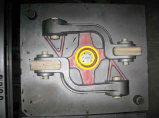
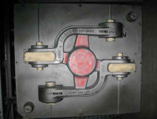
sfsa_s.gif (4934 bytes)

amc.gif (6172 bytes) afs.gif (3195 bytes)

A Design Study in Steel - Spokane Industries Steel Snubber Arm

Final Mold Design

 Cope Pattern Drag Pattern

The photos show the top/cope pattern and the bottom/drag pattern used to make the sand molds.

  • The sections shaded in red show the pouring basin, the gating into the center bars, and the tie rods between the two castings.

  • The sections shaded in light tan show where the cores sit to form the center bores and the gap between the forks.

  • The two yellow circles on the cope pattern show where the pour flask/riser sits in the assembled mold.

The two patterns are positioned in the metal flasks/frames. Then the pour flask (with a ceramic filter) is fitted onto the cope pattern. The top and bottom halves of the mold are formed by packing chemically bonded sand into the metal frames holding the patterns. 

After the sand "cures" into a rigid body, the top and bottom mold sections are matched together "top-to bottom" to form a completed mold.


Back


Next

24


Copyright 2011  by the Steel Founders' Society of America   All rights reserved. 
Address comments to: blairr@sfsa.org
Last Modified:August, 2011 by STG

arrow_top.gif (1191 bytes)
Page 1

In cooperation with
Spokane Industries - Steel Castings Division