SFSA-Logo

AMC  Logo AFS-Logo

An Example in Steel Casting    The Ice Cleat on the M1 Abrams Tank

Parting Line and Orientation
Parting Line and Orientation in the Mold

Design Criteria -- The pattern has to be planned and designed so that –

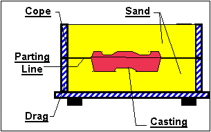
  • The parting line is in the largest cross-sectional plane of the casting.
  • The component face with the greatest surface detail is in the drag, because fluid fill is better in the drag and low-density, non-metallic inclusions tend to segregate in the cope at the top of the casting .
  • The pattern is oriented for continuous, low velocity , non-turbulent fluid flow.
  • The need for cores is minimized or  eliminated.


CopeDrag.gif (3710 bytes)

Schematic of Parting Line in a Sand Mold

Three  pattern orientations and parting line options are shown.
Choose the one that bests meets the design criteria
Parting Line Option 1
Option 1 -- Cleat Up
Parting Line Option 2
Option 2 -- Cleat Down with Curved Parting Line
Parting Line Option 3
Option 3 -- Cleat Down with Straight Parting Line

arrow_forward.gif (1139 bytes)
Back Next

  9

SFSA Last Modified:December, 1998 by STG
Copyright 1995 - '98 by Steel Founders' Society Of America.
All rights reserved. Address Comments to:monroe@sfsa.org
Top