Inspection Standards
Table of Contents
For casting inspection, the criteria considered are surface appearance and integrity, soundness of sections, and accuracy of dimensions. Inspection standards give guidance on inspecting these properties.
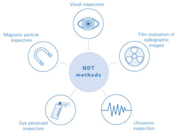
Often, the designer, if they are unfamiliar with the foundry process, may specify a quality level higher than the design requires, which serves no purpose except to increase cost. A more favorable price and delivery can be obtained by first selecting the material specification (preferably ASTM) which meets the mechanical test requirements and whose scope encompasses the service for which the part is intended. Next, the necessary quality level can be established by specifying inspection procedures such as visual, magnetic particle, liquid penetrant, radiography, and ultrasonic.
Non-Destructive Tests (NDTs) (also referred to as Non-Destructive Evaluations (NDEs) or Non-Destructive Inspection (NDI)) can show indications which are possible non-conformities in the casting without destroying it. This means that every part created may be tested for quality. However, there are limitations like time and what certain tests can find. For example, Liquid Penetrant Inspection cannot detect internal casting porosity since the test takes place only at the surface. These limitations will be addressed along with the benefits of each test below.
One thing to note is that NDTs show indications which must be examined further to be deemed non-conformities. Indications must be checked against the standard chosen by the purchaser or against the purchaser’s requirements to determine if they are problematic.
Surface Discontinuities
Surface discontinuities are the irregularities, textures, or cracks that are found on the surface of the casting. Although some are of such a size that they can be seen visually, others are either not visible or require special inspection methods such as magnetic particle or liquid penetrant to be seen. For the examinations to be meaningful as a basis for purchase, all parties concerned must use inspection methods that are standard.
Visual Inspection:
Most ASTM specifications contain a requirement stating that the surface of the casting will be examined visually with the naked eye and free of adhering sand, scale, slag inclusions, porosity, cracks, and hot tears. Visual Method MSS-SP-55, available from the Manufacturers Standardization Society of the Valve and Fittings Industry, may be used to define acceptable surface discontinuities. This standard consists of a series of photographs which are defined as acceptable and unacceptable. Other visual standards may also be used if both parties agree to it.
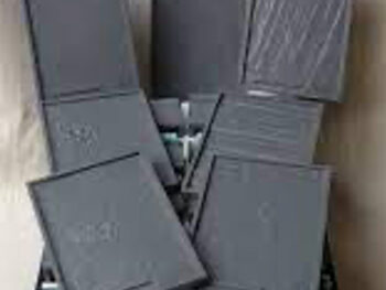
ASTM A802 uses a 31-plate set of SCRATA comparators, available from Castings Technology International, depicting various degrees of surface discontinuities in several categories such as wrinkles, porosity, veining, etc. Under this standard, the purchaser can specify surface requirements by quoting category numbers and levels of appearance. By itself the standard specifies nothing as being acceptable or unacceptable. The comparators are merely points of reference used in communicating a requirement.
Visual Inspection should always be the primary method of inspection no matter what other techniques are required by the purchaser. Visual Inspection is low cost and can be applied while work is in progress. Common pieces of equipment used in visual inspection include a set of surface comparators and a straight edge or a pocket rule.
Visual Inspection has its limitations just like every NDT. The main limitation is that it only looks at the surface. Also, there is no physical, permanent record associated with the test, and application of visual inspection standards is highly subjective. Photos like those in Visual Method MSS-SP-55 help to show inspectors what is acceptable and what is unacceptable, but it is ultimately up to the inspector to say what passes and what does not. This may differ from inspector to inspector which is one of the negatives of Visual Inspection.
Visual Inspection can only be used on surfaces that can be seen. Castings may have internal geometry that can be visually inspected; however, subsurface porosity or cracks cannot be detected. For areas of the casting that cannot be visually seen another method of NDT, such as radiography, may be used. Refer to the Comparison of All NDT’s table at the end of this section to see which NDT test methods allow for subsurface examination.
Dimensional Tolerance Classes:
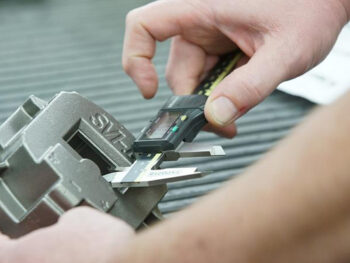
Dimensional tolerances are permissible deviations from the nominal dimension. Deviations from the nominal, or aimed for dimension, may occur for several reasons. The primary source is the contraction of the liquid metal as it solidifies and cools in the mold.
An experienced foundryman can estimate the metal contraction that will occur on any dimension, but only actual production will show precisely how the metal will behave. Tolerances on the production of a single casting or a small run of castings, therefore, tend to be liberal. With castings produced in large numbers, the opportunity exists to make changes in pattern equipment to account more closely for steel shrinkage for the given geometry. In this situation, tighter dimensional tolerances can be achieved, but a slight variation will always exist.
Grinding, gauging, coining, straightening, machining, and other measures are available to achieve a desired tolerance level that cannot be achieved by the casting process alone. Meeting tight dimensional tolerances adds to the price and should only be specified where required. See SFSA Handbook Supplement 3 – Dimensional Tolerances for more information.
Liquid Penetrant Inspection:
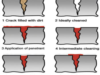
Liquid Penetrant Inspection (LP) relies on dye to penetrate and fill discontinuities that are open to the surface. Later, by applying a developer to the casting the dye penetrant is drawn out of the discontinuities to show visible indications. It is not generally used on “as cast” or shot blasted surfaces because of the likelihood of obtaining false indications. The penetrant method is best suited for use on machined, ground, or very smooth “as cast” surfaces. Liquid penetrant inspection is of particular importance for austenitic alloys because they are non-magnetic and therefore their surfaces cannot be examined by Magnetic Particle Inspection.
Liquid Penetrant testing is easy to execute, is low cost, and is not limited to only magnetic or nonmagnetic materials. To evaluate a part with this method, penetrant and developer are required. These materials are available in commercial kits that can be easily purchased. Fluorescent penetrants are also commonly used in industry; they require ultraviolet light to observe indications.
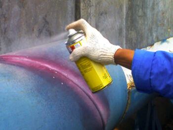
ASTM E165 describes the standard method for conducting this test. A set of reference photographs for acceptance or rejection is contained in ASTM E433. There are no degrees of severity in this standard. When E433 is specified, there must be an agreement of interpretation outlining what is and is not acceptable to prevent subsequent misunderstanding. The purchaser must specify unacceptable dimensions including maximum indication length and maximum number of indications per unit area. ASTM A903 specifies surface acceptance standards for both magnetic particle and liquid penetrant inspection.
Liquid Penetrant Inspection can detect surface discontinuities that are not readily visible to the naked eye. However, it cannot detect any subsurface discontinuities because the dye cannot access them. Like Visual Inspection, using Liquid Penetrant testing with another subsurface test would give a more compete evaluation of the part.
Magnetic Particle Inspection:
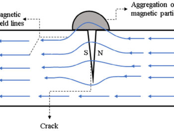
Magnetic Particle Inspection (MPI) is used to detect surface discontinuities and, under ideal conditions, certain discontinuities lying just below the surface. However, this is primarily a surface inspection method. Any conclusion regarding depth or extent of interior discontinuities must be based on exploration by other test methods.
Magnetic Particle Inspection is conducted by polarizing the part being evaluated and covering its surface with magnetic particles applied as dry powder or in a liquid suspension. The magnetic particles then aggregate over the discontinuities. These indications can be seen either with the naked eye (with some difficulty) or under ultraviolet light. Discontinuities that are perpendicular to the magnetic field lines are easy to see, while discontinuities parallel to the magnetic field lines are difficult to see. To account for this, MPI at two test orientations that are 90 degrees from one another is standard in the industry. Multi-dimensional fields (3D magnetization) are another way to see discontinuities hidden in other orientations and is also a standard practice in the industry.
Magnetic particle inspection is described for both dry powder and for wet method in ASTM E709. ASTM A903 details the acceptable surface standards for both Magnetic Particle and Liquid Penetrant Inspection. ASTM E3024 is the standard practice for magnetic particle testing in industrial applications and ASTM E1444 is for aerospace applications.
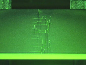
To conduct Magnetic Particle Inspections, commercial equipment to polarize the casting is needed along with the magnetic powder. When the commercial equipment is available, the test is relatively low cost to execute.
Magnetic Particle testing is only applicable to ferromagnetic materials due to the need to polarize the material. Rough surfaces also hinder the ability to identify indications.
ASTM E125 provides a set of reference photographs for different types of casting surface discontinuities as revealed by the dry powder magnetic particle technique. Each type of discontinuity, except for porosity, is classified in five degrees of severity. For porosity, only two examples are given. There is no correlation between degrees of severity between the various types of discontinuities. For instance, degree 3 of type I is not equivalent to degree 3 of type II. By prior agreement between the purchaser and the producer, these photographs may be used as standards to accept or reject castings. The acceptable degree of severity for each type of discontinuity must be spelled out in the purchase order or contract.
Different types of discontinuities do not have equal effects on the serviceability of the casting. An effort should be made to assign realistic acceptance levels to each area of the casting based on the type and magnitude of stresses to which each area is subjected in service. It is difficult to consistently interpret magnetic particle indications on castings against a set of photographic references; consequently, there is a need for cooperation between the manufacturer and the purchaser.
One example is in the linear discontinuity of degrees 1 and 2. The degree 1 indications are approximately 1/2 in. (13mm) long, while those of degree 2 are approximately 5/8 in. (16 mm) in length. The degree 2 causes the powder to cling in a wider pattern. In the interpretation of indications, however, their width is seldom considered; only the length of the indication is compared to the photographic references.Although the separation between degree 1 and degree 2 is completely arbitrary and in no way related to service performance, there is often great concern as to whether the indication is greater than 1/2 in. (13 mm) or less than 5/8 in. (16 mm).
To overcome some of the interpretation problems, some purchasers specify acceptance standards to various degrees in E125 and then add that cracks and not tears shall not exceed 1/2, 1/8, or even 1/16 in. (13, 3, or 1.5 mm) in length. Although these dimensions are somewhat arbitrary, their being specified does eliminate much misunderstanding.
Misunderstanding can be minimized if the inspectors for both parties are at least ASNT (American Society for Nondestructive Testing) Level 1 inspectors. This is a rating of the level of competence to which the individual is certified by training and completion of a prescribed number of classroom hours in inspection techniques and interpretation. The ASME Boiler and Pressure Vessel Code requires that inspectors making interpretations be certified to Level 2, which is a higher qualification than Level 1.
Magnetic particle inspection has probably led to more misunderstanding than any other inspection tool. It has made possible the selection of castings for critical applications with its outstanding ability to detect surface discontinuities. And yet, when improperly applied, it increases the cost of a casting without improving its performance. Therefore, it is essential that standards of acceptance be applied with discretion.
Internal Discontinuities
Internal discontinuities are the irregularities or imperfections that are found inside the casting. These internal discontinuities include gas porosity, shrinkage porosity, and cracks that cannot be seen by Visual Inspection, LP, or MPI and require inspection methods such as Radiographic or Ultrasonic. For the examinations to be meaningful as a basis for purchase, all parties concerned must use inspection methods that are standard.
Radiographic Testing:
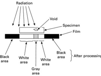
Radiographic Testing (RT) or X-ray examination is used to detect internal macroscopic discontinuities such as cracks, porosity, blow holes, nonmetallic inclusions, and shrinkage. RT is conducted by x-raying a part in front of a special film. The film absorbs x-rays and shows the locations of indications after development. The more material the x-rays need to travel through, the fewer x-rays hit the film. Indications like blow holes and porosity, since they are empty space, do not absorb the x-rays, so more x-rays reach the film resulting in a dark spot. The film gives a permanent record of indications on a part.
X-ray examination is required by many codes and specifications and is useful in the qualification of processes. A commercial x-ray or gamma unit (made especially for inspecting welds, castings, and forgings) is required along with special film and a processing facility. Neither the unit nor the film is cheap, so x-ray use should be limited to those areas where other methods will not provide the assurance required.
X-ray radiation has other limitations that restrict its performance. X-rays are rarely applied fully perpendicular to the film and tend to spread out at an angle. The angle of the x-rays distorts the size and location of the indications. There is also a certain level of skill that is required to choose the angles of exposure, work the operating equipment, and to interpret indications.
Cracks are hard to detect with x-ray since they do not leave empty space in the casting. Unlike blow holes or porosity, cracks do not significantly change the absorption rate of the x-rays compared with the sound base metal. Because of this, they may not be detected.
ASTM E94 is a guide for radiographic testing and replaced E142. Except for a very few isolated cases, no deviation from this guideline need be made. ASTM E1030 is a test method for radiographic testing. Reference radiographs in E242 show how factors such as radiation energy, specimen thickness, and film properties affect the radiographic images.
There are three basic groups of reference radiographs issued by ASTM for evaluation of steel castings; E446 applies to castings up to 2” in thickness (51 mm), E186 applies to 2-4.5” (51-114 mm) thick sections, and E280 applies to wall thickness of 4.5-12” (114-305 mm). A special set of reference radiographs for investment casting is available in ASTM E192.
Reference radiographs become standards for acceptance and rejection after the purchaser and the producer have agreed in the purchase order/contract to the acceptable severity level for each type of discontinuity. The choice of acceptable discontinuity severity level should be based on the design of the casting and the stresses anticipated in service. The lower the specified severity level the more stringent the requirements. Generally, low severity levels are specified for pressure-containing castings with high pressure ratings and wall sections of 1” (25 mm) or less. Likewise, low severity levels are specified for machinery or dynamically loaded casting subject to high fatigue and impact stresses and with wall sections of less than ½” (13 mm). As wall sections increase and as the fatigue and impact stresses experienced are reduced, severity levels become more relaxed. For structural castings which are not dynamically loaded, moderate discontinuity severity levels are usually specified, and for heavier sections of about 3” (76 mm) higher severity levels are usually acceptable. To require quality levels more stringent than what is justified by actual service conditions adds needlessly to the cost of the casting. Also, requiring a single across-the-board severity level for all types of discontinuities should be avoided. Some types of discontinuities are more detrimental than others depending upon the nature of the stresses to which the casting is subject. For instance, severity level 2 might be specified for shrinkage, but severity level 3 specified for gas porosity since it is generally less deleterious to tensile properties. Also, the entire casting need not require radiographic inspection, and the same severity levels need not apply to all areas of the casting. This is governed by the type of stress and the stress levels in each section of the casting. Careful analysis or, at least, good judgment can affect sizable cost savings. The areas to be radiographed with the required severity level should be indicated on the casting drawing.
The severity rating is arbitrary and based on little more than opinion. None of the reference radiographs are based on any test data, and the severity levels are not graded to any basis of acceptability as to service performance. They only serve as a reference point in communicating the purchasers’ requirements.
There is a tendency on the part of some individual company standards to specify films, un-sharpness ratios, densities, and other details aimed at producing perfect films with cost being no object. It should not be forgotten that the radiographic film is a means to an end and not the end itself. It is simply not logical to specify a technique capable of sensitivity which will show discontinuities smaller than the minimum size for rejection.
Reference radiographs of discontinuities common to steel welding are categorized in ASTM E390. However, production welding, which is done by the foundry as a normal part of the casting production process, should be inspected to the same standards employed for the original casting, i.e., E446, E186, or E280. E390 is applicable only to inspection of welds used for cast-weld inspection and not to casting production welds.
Ultrasonic Testing:
Although the ultrasonic method of inspection has not been in common use for as long as radiographic methods, it nevertheless is a valuable tool for examining heavy wall castings for internal discontinuities.
Ultrasonic Testing (UT) is completed in two methods: either (1) by sending an ultrasonic pulse through the material and observing when the pulse returns to the transmitter/receiver (pulse-echo technique); or (2) by sending a continuous transmission through the part with a receiver on the other side (through-transmission technique). To perform UT, special commercial equipment, either of the pulse-echo or transmission type, and a couplant gel is needed.
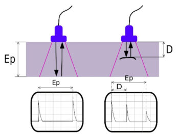
For the Pulse-Echo, the pulses are plotted on a graph showing intensity over time. If there are no cavities or cracks in the piece, the transmission pulse and the backwall echo are the only spikes seen. If there is a cavity or crack within the material, the echo pulse will return early as it did not travel through the entire part. A couplant gel is required to allow the ultrasonic pulses to flow into the material and must be applied to the surface the transmitter/receiver will be placed on. Ultrasonic Testing can find many sub-surface discontinuities, including those too small to be detected by other methods, and especially subsurface, planar discontinuities. Ultrasonic testing provides a high level of sensitivity and accuracy which helps detect very small discontinuities.For Through-Transmission, the couplant gel is once again required, but instead of looking at the echo, you are looking to receive the signal on the other side. If the transmission pulse is not received, there is a discontinuity in the location that is blocking the ultrasonic pulse.
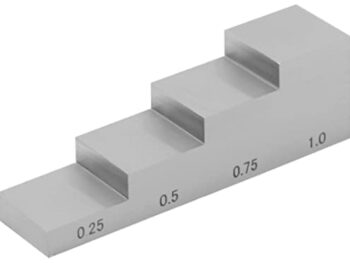
Ultrasonic Testing is invaluable in detecting discontinuities in heavy sections and in joints that are inaccessible to Radiographic Testing. Since no picture, in the usual sense, of the discontinuity is obtained, considerable judgment must be exercised in interpretation of signal displayed on the screen. The interpretation of the results takes a high level of skill since there is no image or permanent record of where indications are or what they are. To aid the interpreter, calibration blocks can be scanned. The blocks have flat bottomed holes at different depths which gives the interpreter an idea of how deep discontinuities are within the part. Following the standard practices for Ultrasonic Testing for castings (carbon, low-alloy, and martensitic stainless steels) in ASTM A609 helps the interpreter and ensures consistency between parts.
One approach in the examination of large heavy wall castings when ultrasonic evaluation may not be acceptable to the purchaser is to first inspect by ultrasonic, then to radiograph only those areas where a suspicious ultrasonic indication is found. Another possibility, since radiography does not reveal the depth of a discontinuity, is to follow radiography with ultrasonic in order to determine and evaluate the depth of the discontinuity.
More recently phased array ultrasonic testing has been used and allows the beam to sweep over a range of angles instead of the fixed angle in conventional UT. Phased array is the same technology used in medical ultrasounds. It can create a 2D image similar to radiography that can be saved in the permanent record of the casting and gives a more detailed picture of what is going on inside a casting than traditional UT.
Comparison of All NDTs
| Advantages | ||||
| Visual Inspection | Liquid Penetrant | Magnetic Particle | Radiography | Ultrasonic |
| Low cost | Easy to use | Permits controlled sensitivity | When the indications are recorded on film, gives a permanent record | Very Sensitive |
| Applicable to magnetic and nonmagnetic materials | Applicable to magnetic, and nonmagnetic materials | Relatively low cost method | Applicable to magnetic and nonmagnetic materials | Applicable to magnetic and non-magnetic materials |
| Can be done while work is in process | Low cost | Allows for subsurface inspection | Permits probing of joints inaccessible to radiography | |
| Limitations | ||||
| Visual Inspection | Liquid Penetrant | Magnetic Particle | Radiography | Ultrasonic |
| Applicable to surface discontinuities only | Only discontinuities open to the surface are detectable | Applicable to ferromagnetic materials only | Requires skill in choosing angles of exposure, operating equipment, and interpreting indications | Requires high degree of skill in interpreting pulse-echo patterns |
| Requires skill in interpretation of indications and recognition of irrelevant patterns | Requires safety precautions | Permanent record is not readily obtained | ||
| Difficult to use on rough surfaces | Cracks difficult to detect | |||
| Equipment Required | ||||
| Visual Inspection | Liquid Penetrant | Magnetic Particle | Radiography | Ultrasonic |
| Surface comparator | Commercial kits, containing fluorescent or dye penetrants and developers | Special commercial equipment | Commercial x-ray or gamma units, made especially for inspecting welds, castings, and forgings | Special commercial equipment, either of the pulse-echo or transmission type |
| Pocket rule | Application equipment for the developer | Magnetic powders – dry or wet form; may be fluorescent for viewing under ultraviolet light | Film and processing facilities | |
| Straight edge | A source of ultraviolet light – if fluorescent method is used | |||
| Workmanship standards | ||||
| Enables Detection of | ||||
| Visual Inspection | Liquid Penetrant | Magnetic Particle | Radiography | Ultrasonic |
| Surface discontinuities – cracks, porosity, slag inclusions, adhering sand, scale, etc. | Surface discontinuities not readily visible to the unaided eye | Excellent for detecting surface and subsurface discontinuities to approximately ¼” below the surface – especially cracks | Internal macroscopic flaws – cracks, porosity, blow holes, non-metallic inclusions, shrinkage, etc. | Sub-surface discontinuities, including those too small to be detected by other methods |
| Especially for detecting subsurface, planar discontinuities | ||||
| Remarks | ||||
| Visual Inspection | Liquid Penetrant | Magnetic Particle | Radiography | Ultrasonic |
| Elongated discontinuities parallel to the magnetic field may not show; for this reason the field should be applied from two directions at or near right angles to each other | Radiographic inspection is required by many codes and specifications | |||
| Useful in process qualification | ||||
| Because of cost, its use should be limited to those areas where other methods will not provide the assurance required | ||||
| Important Specs/Documents: | ||||
| Visual Inspection | Liquid Penetrant | Magnetic Particle | Radiography | Ultrasonic |
| ASTM A802 Standard Practice for Steel Castings, Surface Acceptance Standards, Visual Examination | ASTM E165 Standard Practice for Liquid Penetrant Testing for General Industry | ASTM E125 Standard Reference Photographs for Magnetic Particle Indications on Ferrous Castings | ASTM E94 Standard Guide for Radiographic Examination Using Industrial Radiographic Film | ASTM A609 Standard Practice for Castings, Carbon, Low-alloy, and Martensitic Stainless Steel, Ultrasonic Examination Thereof |
| SCRATA Comparator Plates – for establishing mutually agreeable acceptance criteria for a specific part | ASTM E433 Standard Reference Photographs for Liquid Penetrant Examination | ASTM E709 Standard Guide for Magnetic Particle Examination | ASTM E186 Standard Reference Radiographs for Heavy-Walled (2 to 4-1/2 in. (50.8-114mm)) Steel Castings | ISO 4992 Steel Castings – Ultrasonic Testing – Part 1: Steel Castings for General Purpose |
| ISO 11971 Steel and Iron Castings – Visual Examination of Surface Quality | ASTM A903 Steel Castings, Surface Acceptance Standards, Magnetic Particle and Liquid Penetrant Inspection | ASTM A903 Steel Castings, Surface Acceptance Standards, Magnetic Particle and Liquid Penetrant Inspection | ASTM E192 Standard Reference Radiographs of Investment Steel Castings for Aerospace Applications | MSS SP-94 Quality Standard for Ferritic and Martensitic Steel Castings and Forgings for Valves, Flanges, Fittings, and Other Piping Components – Ultrasonic Examination Method |
| MSS SP-55 Quality Standard for Steel Castings for Valves, Flanges, and Fittings, and Other Piping Components (Visual Method for Evaluation of Surface Irregularities) | ISO 3452-1 Non-Destructive Testing – Penetrant Testing – General Principles | ASTM E1444 Standard Practice for Magnetic Particle Testing for Aerospace | ASTM E280 Standard Reference Radiographs for Heavy-walled (4-1/2 to 12 in. (114-305mm)) Steel Castings | |
| ISO 4987 Steel Castings – Liquid Penetrant Inspection | ASTM E3024 Standard Practice for Magnetic Particle Testing for General Industry | ASTM E446 Standard Reference Radiographs for Steel Castings up to 2 in. (50.8mm) in Thickness | ||
| MSS SP-93 Quality Standard for Steel Castings and Forgings for Valves, Flanges, Fittings, and Other Piping Components – Liquid Penetrant Examination Method | ISO 4986 Steel Castings – Magnetic Particle Inspection | ASTM E1030 Standard Practice for Radiographic Examination of Metallic Castings | ||
| MSS SP-53 Quality Standard for Steel Castings and Forgings for Valves, Flanges, Fittings, and Other Piping Components – Magnetic Particle Examination Method | ASTM E1742 Standard Practice for Radiographic Examination | |||
| ASTM E2007 Standard Guide for Computed Radiography | ||||
| ASTM E2033 Standard Practice for Radiographic Examination Using Computed Radiography (Photostimulable Luminescence Method) | ||||
| ASTM E2660 Standard Digital Reference Images for Steel Castings for Aerospace Applications | ||||
| ASTM E2868 Standard Digital Reference Images for Steel Castings up to 2 in. (50.8 mm) in Thickness | ||||
| ASTM E3030 Standard Digital Reference Images for Heavy-Walled (2 to 4-1/2 in. (50.8-114mm)) Steel Castings | ||||
| ASTM -In Progress: Standard Digital Reference Images for Heavy-walled (4.5 to 12 in.) Steel Castings | ||||
| ISO 4993 Steel and Iron Castings – Radiographic Testing | ||||
| ISO 5579 Non-Destructive Testing – Radiographic Testing of Metallic Materials Using Film and X- or Gamma Rays – Basic Rules | ||||
| MSS SP-54 Quality Standard for Steel Castings for Valves, Flanges, Fittings, and Other Piping Components – Radiographic Examination Method | ||||
Testing and Inspection Specification Table
| Mechanical Testing | Methods and Definitions |
| ASTM A370 | Standard Test Methods and Definitions for Mechanical Testing of Steel Products |
| ASTM E208 | Standard Test Method for Conducting Drop-Weight Test to Determine Nil-Ductility Transition Temperature of Ferritic Steels |
| Welding | Qualification of Procedures and Personnel |
| ASTM A488 | Recommended Practice for Qualification of Procedures and Personnel for Welding of Steel Castings |
| ASME Section IX | Welding and Brazing Qualifications |
| Visual Inspection | Procedure |
| ASTM A802 | Standard Practice for Steel Castings, Surface Acceptance Standards, Visual Examination |
| ISO 11971 | Steel and Iron Castings – Visual Examination of Surface Quality |
| Visual Inspection | Reference Photgraphs |
| MSS-SP-55 | Quality Standard for Steel Castings for Valves, Flanges, and Fittings, and Other Piping Components (Visual Method for Evaluation of Surface Irregularities) |
| SCRATA Comparators | Steel Casting Research and Trade Association (SCRATA) Comparator Plates |
| Liquid Penetrant | Procedure |
| ASTM A903 | Steel Castings, Surface Acceptance Standards, Magnetic Particle and Liquid Penetrant Inspection |
| ASTM E165 | Standard Practice for Liquid Penetrant Testing for General Industry |
| ISO 3452-1 | Non-Destructive Testing – Penetrant Testing – General Principles |
| ISO 4987 | Steel Castings – Liquid Penetrant Inspection |
| MSS SP-93 | Quality Standard for Steel Castings and Forgings for Valves, Flanges, Fittings, and Other Piping Components – Liquid Penetrant Examination Method |
| Liquid Penetrant | Reference Photographs |
| ASTM E433 | Reference Photographs for Liquid Penetrant Inspection |
| Magnetic Particle | Procedure |
| ASTM A903 | Steel Castings, Surface Acceptance Standards, Magnetic Particle and Liquid Penetrant Inspection |
| ASTM E709 | Standard Guide for Magnetic Particle Examination |
| ASTM E1444 | Standard Practice for Magnetic Particle Examination for Aerospace |
| ASTM E3024 | Standard Practice for Magnetic Particle Testing for General Industry |
| ISO 4986 | Steel Castings – Magnetic Particle Inspection |
| MSS SP-53 | Quality Standard for Steel Castings and Forgings for Valves, Flanges, Fittings, and Other Piping Components – Magnetic Particle Examination Method |
| Magnetic Particle | Reference Photographs |
| ASTM E125 | Reference Photographs for Magnetic Particle Indications |
| Radiography | Procedure |
| ASTM E94 | Standard Guide for Radiographic Examination Using Industrial Radiographic Film |
| ASTM E142 | Standard Method for Controlling Quality of Radiographic Testing |
| ASTM E1030 | Standard Practice for Radiographic Examination of Metallic Castings |
| ASTM E1742 | Standard Practice for Radiographic Examination |
| ASTM E2007 | Guide for Computed Radiography |
| ASTM E2033 | Standard Practice for Radiographic Examination Using Computed Radiography (Photostimulable Luminescence Method) |
| ISO 4993 | Steel and Iron Castings – Radiographic Testing |
| ISO 5579 | Non-Destructive Testing – Radiographic Testing of Metallic Materials Using Film and X- or Gamma Rays – Basic Rules |
| MSS SP-54 | Quality Standard for Steel Castings for Valves, Flanges, Fittings, and Other Piping Components – Radiographic Examination Method |
| Radiography | Reference Photographs |
| ASTM E186 | Standard Reference Radiographs for Heavy-Walled (2 to 4-1/2 in.) Steel Castings (3 Sets; X-ray, Gamma Rays, Betatron) |
| ASTM E192 | Reference Radiographs for Investment Steel Castings for Aerospace Applications |
| ASTM E242 | Reference Radiographs for Appearances of Radiographic Images as Certain Parameters are Changed |
| ASTM E280 | Standard Reference Radiographs for Heavy-Walled (4-1/2 to 12 in.) Steel Castings (2 Sets; X-ray, Betatron) |
| ASTM E390 | Reference Radiographs for Steel Fusion Welds |
| ASTM E446 | Standard Reference Radiographs for Steel Castings up to 2 in. in Thickness (3 Sets; X-rays, Iridium, Cobalt) |
| ASTM E2660 | Standard Digital Reference Images for Steel Castings (Aerospace Investment) |
| ASTM E2868 | Standard Digital Reference Images for Steel Castings up to 2 in. (50.8 mm) in Thickness |
| ASTM E3030 | Standard Digital Reference Images for Heavy-Walled (2 to 4-1/2 in.(50.8-114mm)) Steel Castings |
| ASTM -In Progress | Standard Digital Reference Images for Heavy-walled (4.5 to 12 in.) Steel Castings |
| Ultrasonic | Procedure and Standards |
| ASTM A609 | Standard Practice for Castings, Carbon, Low-alloy, and Martensitic Stainless Steel, Ultrasonic Examination Thereof |
| ISO 4992 | Steel Castings – Ultrasonic Examination |
| MSS SP-94 | Quality Standard for Ferritic and Martensitic Steel Castings and Forgings for Valves, Flanges, Fittings, and Other Piping Components – Ultrasonic Examination Method |
