An Example in Steel CastingHinge/Bearing Assembly for Log Forwarder
Hinge Plate
Final Design of the Cope and Drag Patterns
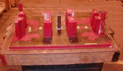
Cope Pattern for the Hinge Plate
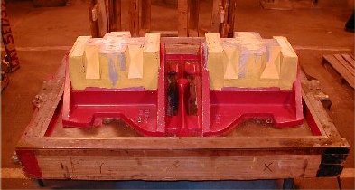
Drag Pattern for the Hinge Plate
The photos above show the patterns for making the cope
and the drag molds for the hinge plate. The mold design uses a horizontal parting line
along the main plate.
The mold is a “2-on” design producing two
castings for each pour. Molten metal feeds down a single center sprue and feeds through
two gates into each plate.
There are four square risers positioned over each
plate and shown in red in the cope photo.
The side walls face down in the drag mold. Three cores
produce the center cavity and the two inner flange walls for each casting. The yellow
cores are positioned to show their placement in the drag mold
Copyright 2000 by the Steel Founders'
Society of America
All rights reserved.
Address comments to: monroe@sfsa.org
Last Modified:September, 2000 by STG